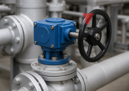
If you have ever stood near a large pipeline and watched someone spin a big handwheel to control flow, there is a good chance a butterfly valve gearbox was doing most of the work behind that handwheel. Most people notice the wheel. Nobody really thinks about what is happening inside that housing attached to the valve.
This blog covers exactly how a butterfly valve gearbox works, what goes on inside it, and which actuation type fits which kind of job.
Why a Butterfly Valve Even Needs a Gearbox
A butterfly valve works by rotating a disc sitting inside a pipe. Quarter turn of the stem and the flow either opens up or shuts off. On a small valve, an operator can do that with two fingers.
The problem starts when valve sizes go past DN200. The disc gets bigger and heavier. Live pipeline pressure pushes hard against that disc face. At that point, trying to rotate the stem manually without any mechanical help is either very difficult or simply not possible for one person standing there.
A butterfly valve gearbox handles this problem. It takes the modest input from a handwheel or a motor and turns it into the high output torque needed to move that disc against pressure without breaking a sweat.
What Actually Sits Inside the Housing
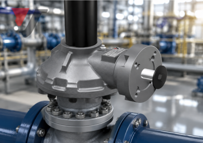
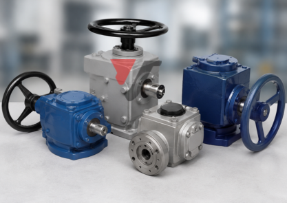
Crack open a standard butterfly valve gearbox, and the internal arrangement is not as complicated as people expect. The main parts you will find are:
- Worm shaft -the input side, connected to your handwheel or actuator drive
- Worm wheel -a larger gear that meshes with the worm shaft and carries the output rotation
- Output shaft -connects directly to the valve stem and physically turns the disc
- Housing -cast iron, ductile iron, or steel, depending on the service environment
- Mechanical stops -hard limiters that block rotation beyond the valve travel range
- Position indicator -tells you whether the disc is sitting open, closed, or somewhere between
The worm shaft and worm wheel pairing is what makes the whole thing work. The worm shaft runs at an angle into the worm wheel, and that geometry is where the torque multiplication comes from.
How Torque Travels Through the Gearbox
Most people never think about this part. Worth understanding properly, though.
When the handwheel turns, the worm shaft rotates with it. The teeth on the worm shaft push against the teeth on the worm wheel. Because the worm wheel carries a much larger diameter and far more teeth, a full rotation of the worm shaft only moves the worm wheel by a small amount. That small movement carries a lot of force behind it.
That output rotation then passes through the output shaft straight into the valve stem. Stem turns the disc. Flow responds.
The gear ratio controls how much torque multiplication the butterfly valve gearbox delivers. A 40:1 ratio means the handwheel needs 40 full turns to produce one quarter-turn of the valve disc. More turns to complete the operation, but the physical effort each turn demands is very manageable.
This path -input shaft into worm, worm into wheel, wheel into output shaft, output shaft into valve stem -stays identical whether the gearbox is running under a handwheel or being driven by a motor.
Self-Locking and Why Operators Appreciate It
Worm gear-based butterfly valve gearboxes carry a built-in advantage that does not get talked about enough. They self-lock.
Because of the angle relationship between the worm shaft and the worm wheel, the system physically cannot be driven backwards. Pipeline pressure pressing against the disc face cannot rotate the valve on its own. The gearbox holds the disc exactly where it was left, no brake required, no extra locking mechanism needed.
This characteristic makes a butterfly valve gearbox particularly dependable for applications where the valve must stay put reliably, like water treatment isolation duties, fire protection headers, and process shutoff lines.
Three Ways to Drive a Butterfly Valve Gearbox
Different sites and different applications call for different ways to drive the gearbox input. Here are the three main options:
Manual handwheel actuation puts an operator directly in control. Turning the handwheel rotates the worm shaft input by hand. Works well for valves that do not need frequent cycling and for locations where a power supply is not available. Nothing to maintain on the actuation side and nothing to fail either.
The electric actuator drive replaces the handwheel with a motor that receives a signal from a control panel or distributed control system. Used heavily in remote or automated plants where someone cannot walk out and operate every valve manually. A butterfly valve gearbox built for this will carry an ISO 5211 mounting pad on the input face for clean actuator attachment.
Pneumatic actuator drive uses compressed air to turn the input shaft. Common in hazardous area classifications where running electric actuators requires explosion-proof certification. Pneumatic drives also respond faster than electric ones, which suits applications needing a quick open or close on demand.
Most butterfly valve gearbox designs accept all three drive types through the same input interface. That flexibility means the actuation method can be changed later without pulling the gearbox off the valve.
Mechanical Stops and Position Indication
Every butterfly valve gearbox ships with mechanical stops fitted inside. These are physical blocks that prevent the output shaft from rotating past the valve’s designed travel limits in either direction.
Over-rotation causes real damage. The disc can jam against the pipe bore, the seating surface takes a hit, or the stem warps under the load. Mechanical stops remove that risk completely by physically ending rotation at both the open and closed positions.
Position indicators mount onto the output shaft and show the disc angle visually. Basic units carry a pointer and a marked scale. Higher specification butterfly valve gearbox assemblies include switchboxes wired back to the control room, confirming open or closed status without anyone needing to walk out to the valve.
Industries That Use Butterfly Valve Gearboxes Regularly
A butterfly valve gearbox turns up across a wide range of industries and applications:
- Water and wastewater treatment plants
- Oil and gas pipelines and processing facilities
- Power station cooling water systems
- Large commercial HVAC installations
- Chemical and petrochemical process lines
- Fire protection and suppression systems
Wherever a large diameter butterfly valve needs controlled and repeatable operation, a gearbox is almost always part of the assembly, sitting between the valve and the operator.
FAQs
Q1. At what valve size does a butterfly valve gearbox become necessary?
Generally, from DN200 upward, though pressure class and operating frequency also push that decision.
Q2. Can manual gearboxes be upgraded to electric actuation later?
Yes, easily, as long as the gearbox has an ISO 5211 compatible mounting pad on the input side.
Q3. Why does a worm gear gearbox not back-drive under pressure?
The worm and wheel geometry makes reverse rotation mechanically impossible under normal pipeline loads.
Q4. How long do butterfly valve gearboxes typically last in service?
With correct sizing and regular lubrication, most units run well beyond 20 years in standard conditions.
Q5. What does a higher gear ratio actually mean for the operator?
More handwheel turns to complete the operation, but significantly less effort is needed on each individual turn.